A quick, cheapest and easiest way of measuring temperature with high precision using DS18B20 sensor from Maxim Integrated, 3$ USB to RS232-TTL converter and a windows PC.
In earlier post I described interfacing DS18B20 programmable digital temperature sensor with ESP8266 NodeMCU board and displaying temperature on OLED display. That required knowledge of programming, basic electronics and required a bit of electronics hardware too. Here, I managed (with the help of several google searches ;)) to interface the DS18B20 with my laptop using cheaply available USB to RS232 converter. And with the help of free software "OneWireViewer" from Maxim Integrated; we can program resolution, view temperature readings or save the data in text or excel files. The best thing is we do not need any microcontroller, microprocessor, Arduino or Raspberry PI etc.
Note:- I am using following abbreviations for personal ease-
UTC = USB to RS232 TTL Converter
DS =DS18B20
[A] Installing drivers for USB to RS232 TLL converter (UTC) with Prolific PL2303HX IC.
Getting these cloned, cheap UTC to work in Windows is a bit tricky. We need to have right drivers to get it detected in our Device Manager of windows PCs.
The working drivers for windows 7 and 8.1 can be found here. Download this zip file and extract to some known folder. May be these work also with windows 10 etc, I would be happy to know results if someone tries this.
(following sequence is for windows 8.1 PC - similar procedure needs to be followed for Windows versions).
1) Press Windows button of your PC and search for Device Manager
2) Open Device manager and expand Ports (COM & LPT) section. Insert UTC into USB port of the PC.
3) After sometime, if drivers for the UTC are not present on your PC, an error will be indicated by Yellow triangle next to "Prolific USB to Serial Comm Port (COMxx)".... Do not Panic.
4) Follow sequences as shown in my video starting here
5) After installation of drivers, Yellow triangle should disappear- note down the COM port number for later use.
6) After installation of drivers for converter, download the OneWireViewer PC interface software from official page of Maxim here. Choose correct operating system of your PC and whether it is 64bit or 32 bit OS.
7) Follow Step B for hardware wiring between DS and UTC
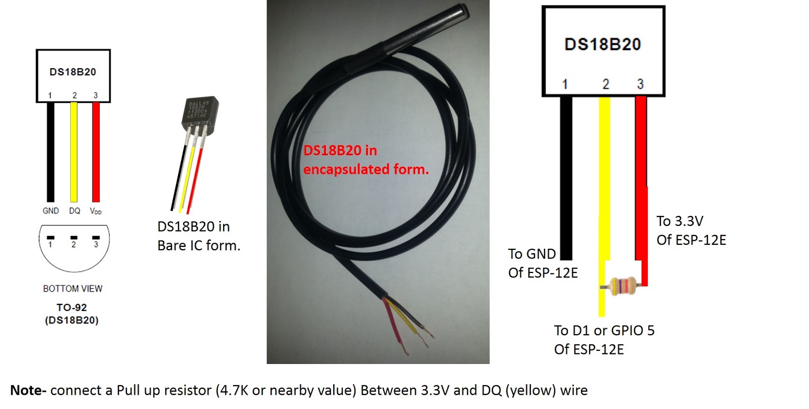
[B] Hardware connections between DS18B20 and USB to RS232 TLL converter (UTC)
1) Since DS18B20 is a 1-wire device/sensor that can be powered in Parasite mode, I have shorted the Receive (RXD) and Transmit (TXD) pins of UTC and connected it to data or DQ (Yellow wire/pin 2) of DS18B20.
2) The ground GND (Black wire/pin 1) and Power VDD (Red wire/pin 3) are shorted together and connected to ground GND of UTC.
Refer my video section here for exact wire connections and pin information.
[C] OneWireViewer software from Maxim to read the temperature from DS18B20
** First remove the UTC from USB port of your PC during installation of OneWireViewer software.
1) Download the OneWireViewer and drivers from the official page of Maxim Integrated for 1-wire/iButton sensors, here.
2) After installing the software+drivers, Insert UTC into USB port and make connections between UTC and DS. and open the OneWireViewer software.
3) Once software starts for the first time, it asks for the Adapter name and USB port number, refer this section of my video.
4) Insert the COM port number that we had noted in step [A - 5] above and click OK.
5) On the Top left side, you should see the unique 64bit ID of the connected DS18B20, click on that and then on the tab named Real-time Temperature and explore other settings.... to enjoy temperature readings :).
[D] Bill of materials
1) DS18B20 from http://aliexpress.com Link
2) USB to RS232 TTL converter with Prolific PL2303HX IC from www.amazon.it Link
3) Few Male-Female SIL Socket Row Strip PCB Connector from www.banggood.com Link
4) 2 Wires, soldering equipment and other accessories.
Copyright (c) 2020 By Electromania blog - https://theelectromania.blogspot.com/ No content of this blog should be copied, distributed, printed without prior permission from owner of this blog.
ESP8266 ESP-12E NodeMCU and DS18B20 based digital thermometer displayed in degree C/F on SPI OLED display. Programmed using Arduino IDE, Adafruit GFX Library.
This Project demonstrates quick and easy approach of reducing
power consumption by around 60-70% for ATMEGA 328P based Arduino boards interfaced with PIR or PID sensors for motion detection. [Part B]
As a comparison, standard digital input pin StateChangeDetection sketch (Examples- Digital- StateChangeDetection) is used to investigate differences in power consumption of PIR sensor module and arduino nano. [Part A]
We will learn following things-
1) Interfacing Pyroelectric/Passive Infra red (PIR) motion
sensor with arduino (or any microcontroller)
2) Using Interrupts of arduino boards (here Arduino NanoV
3.0 clone ) to detect output of PIR sensor
3) Extending battery life or reducing power consumption by
putting arduino nano into deep sleep or hibernation when motion is not detected
by PIR sensor.
Pyroelectric/Passive infrared (PIR) sensors
are widely used in Automatic doors or lights, surveillance cameras, toys, night
lamps, automatic cameras etc. We can easily recognize such PIR sensors around
us, because these sensors mostly have typical hemispherical dome with honeycomb
like small facets (Fresnel
lens) all around its body.
Rattlesnakes have natural "invisible heat" or
"infrared radiation" sensor on its head, It can sense extremely tiny
variations in surrounding temperatures. This helps the snake to detect its prey
without actually "seeing" it, just by "sensing" the warmth
of the body of its prey. Electronic PIR sensors work in similar manner.
PIR sensors are used to generate electronic signal output
upon detection of any human/animal movement within the vicinity of sensor's
detection range. These sensors detect minute changes in surrounding temperature
emitted in the form of infrared
radiation (IR radiations) by our bodies. Every object above above
absolute zero degree temperature ( −273.15°) emits IR radiations. Special kind
of pyroelectric materials
are used in these sensors which generate temporary electrical voltage depending
on variations in its temperature. Therefore, PIR sensors are called passive
sensors, i.e. they do not consume energy for detection purpose; but they catch
energy (Infrared radiations) emitted by other bodies . This makes PIR sensors
useful for applications where mechanical, magnetic or light sensors cannot be
used for one or the other reason.
The PIR sensor used in this project is purchased from banggood.com with following features:-
*Detection range of 3 to 7m,
*Possibility to adjust its output ON state duration
from 5 to 200 sec
*Operating input voltage between 4.5 to 20 V.
*Predicted
idle state current consumption is less than 60 micro-Amps.
*Output of PIR
sensor is 3.3V TTL logic level making it compatible also with ESP8266, arduino
Due (apart from arduino uno, nano etc) and other boards operating at 3.3V
logic levels. No need of logic level converters.
Typical operation is as follows-
1) Output remains LOW in idle state
2) Output goes HIGH (3.3V) when motion is detected by sensor
i.e. if anybody moves within its detection range
(Detection range or Sensitivity can be adjusted by Sx or
sensitivity potentiometer)
3) Output remains HIGH for fixed time set by Tx or time
setting potentiometer.
The output of sensor can be given as intput to
microcontrollers, processors, logic level ICs, data acquisition systems,
MOSFETs etc.
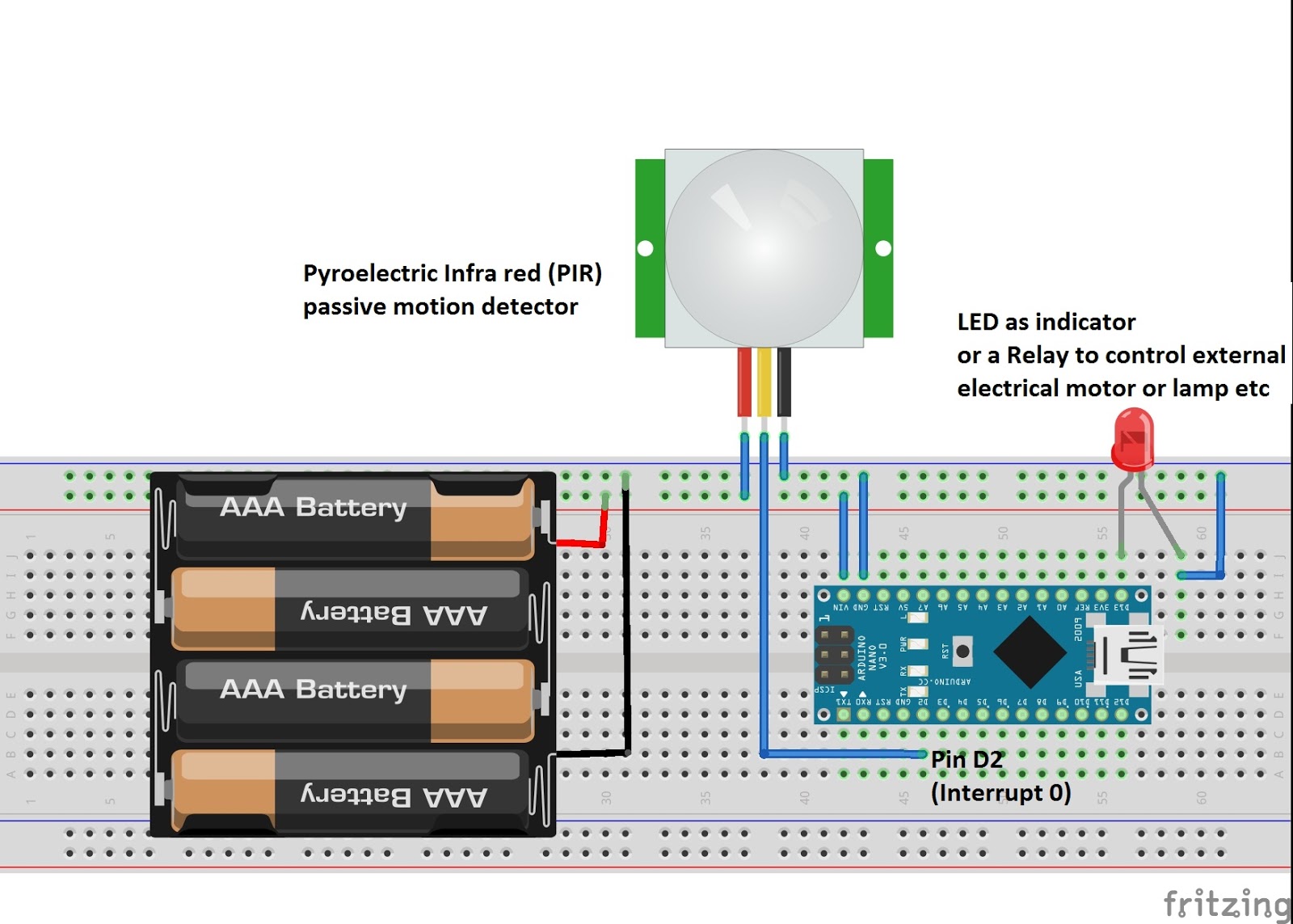
Connection diagram and components:
Connections are shown in fritzing circuit diagram on the left.
Since, we will be using hardware
interrupt of arduino nano board, I have connected output of PIR sensor
to pin D2 (or interrupt 0). Arduino nano has two interrupt pins, pin D2 and D3
for interrupt 0 and 1 respectively.
We will read PIR sensor output using "hardware
interrupt" functionality of arduino. Interrupts help in letting our
arduino do its regular job or sleep into deep hibernation mode until some
signal is received at its interrupt pins. This lets us use arduino perform
other tasks or remain in "nearly OFF state" while waiting for signal
at interrupt pins. This helps in reducing power consumption of arduino and
sensor system.
Bill of materials (BoM)-
1) PIR sensor
2) 1) Arduino Nano V 3.0 board ( or other boards can be
used, provided interrupt pins are selected accordingly- read more )
-For Zero, MKR1000- all digital pins, except pin 4
-For Due- all digital pins
2) Breadboard or PCB
3) Power supply or battery with at least 5.5V since we will
be powering arduino from VIN pin
4) Jumper wires at least 5
5) LED or relay to connect to output pin (here pin D13) of
arduino
[A] Traditional method: pin state change detection mode (Higher power consumption)
This sketch is given on my instructable page here.
Before going to main concept of using interrupt and power
saving deep sleep mode, let us briefly understand power consumption using Pin
state change polling sketch.
I have slightly, modified the standard sketch available in Examples section of Arduino IDE.
In this sketch, we are continuously reading/polling the
input pin D2 to which output of PIR sensor is connected.
The arduino never goes to sleep mode, ADCs are enabled,
hence continuously consumes maximum power.
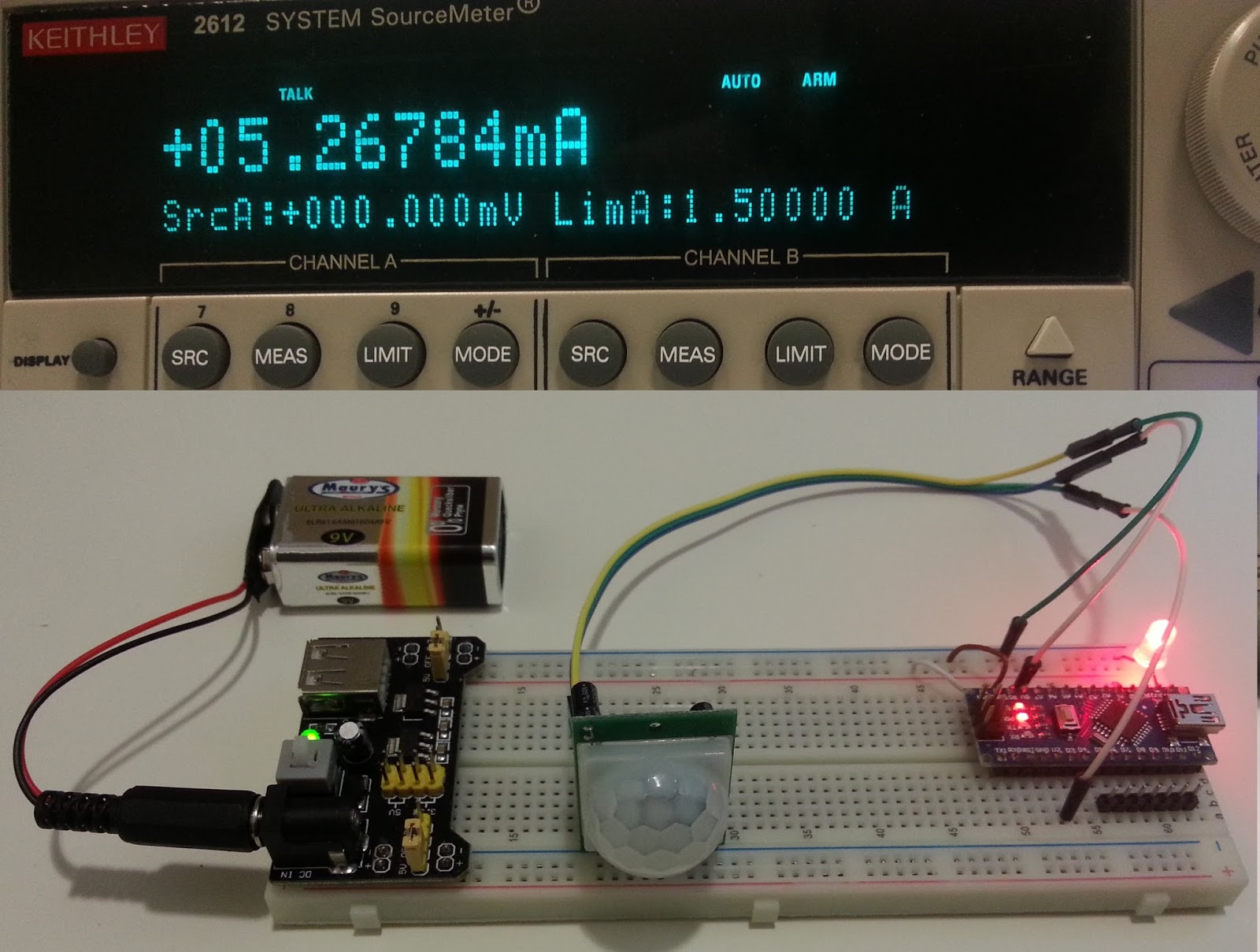
The current and power consumption is as follows-
* No motion detected by PIR sensor - external LED at pin D13
is OFF:- 12.87milliAmp / 62.45 mWatt
* Motion detected by PIR sensor - external LED at pin D13 is
turned ON:- 36.55 milliAmp / 175 mWatt
Considering it is continuously in OFF state and no motion
detected:-
* Typical 9V battery ( approx 500mAh) will last
for 500/12.87 = 38 hours
* Typical AA size batteries(approx 2500mAh) will last
for 2500/12.87 = 195 hours or 8 days
[B] Power saving mode: Interrupt driven Sleep and Wakeup (Lowest power consumption mode)
This sketch is available here. and at the end of this post.
To save power/battery consumption, it would be beneficial to
put arduino into lowest power consumption mode i.e. Deep Sleep or Hibernation until PIR sensor
detects motion. We will achieve this using hardware interrupt and Power Down
Mode of arduino board's ATMEGA328P microcontroller. Moreover, we will disable
analog to digital converters (ADC) since we do not need any ADC.
"The Power-down mode saves the register contents but
freezes the Oscillator, disabling all othe r chip functions until the nex t
interrupt or hardware reset." text from ATMEGA328 datasheet.
In this sketch, we are using input pin D2 or Interrupt 0 to
which output of PIR sensor is connected. (you can also use pin D3 i.e. interrupt 1, and for other boards different pins as mentioned here).
Since PIR detector itself has ON state timer, we do not need
any timer from arduino to keep output pin D13 ON for fixed time. The ON time
can be physically adjusted using Tx potentiometer, as shown in previous step.
-When PIR sensor detects motion, PIR sensor output state
changes from LOW to HIGH. This rising edge signal is picked up by interrupt 0,
arduino Awakes from sleep mode, interrupts are disabled temporarily and
consequently pin D13 goes HIGH.
Once, set time is passed, PIR output again reverts back to
LOW from HIGH, this falling edge signal raises another interrupt, putting
arduino into hibernation once again.
- Arduino on first power ON, blinks LED at pin 13 for a
minute, this is just for visual indication of warm-up period required by PIR
sensor to stabilize to ambient temperature.
for( int i = 1; i <= 120; i++) {
digitalWrite(LedPin, HIGH);
delay(100);
digitalWrite(LedPin, LOW); delay(100); }
-The Arduino is kept into Hibernation until D2 pin is LOW.
In function
Hibernate();
-we will configure all pins as INPUT, except pin 13 to which we have
connected our LED or relay.
for (int i = 0; i < 20; i++) {
if(i != 13)
pinMode(i, INPUT);}
-set arduino sleep mode to lowest power consumption mode
set_sleep_mode(SLEEP_MODE_PWR_DOWN);
-disable ADCs
ADCSRA &= ~(1 << 7);
-disable Brown out detector used to check input voltage
level
sleep_bod_disable();
-we attach interrupt 0 of pin 2 into detect CHANGE in state
of signal at pin 2
Let us analyze power consumption with hibernation and interrupt based sketch:
The current and power consumption reduces drastically using:
power down mode, putting all pins to INPUT (or OUTPUT) and disabling ADCs.
* No motion detected by PIR - external LED at pin D13 is OFF
(Arduino Hibernated) :- 5 milliAmp / 25 mWatt
* Motion detected by PIR - external LED at pin D13 is turned
ON (Awake):- 32 milliAmp / 167mWatt
Considering it is continuously in OFF state and no motion
detected:-
A typical 9V battery considering giving
500mAh, will last for 500/5 = 100 hours or 4 days
a typical AA size batteries giving 2500mAh,
will last for 2500/5 = 500 hours or 21 days
We have reduced OFF state power consumption from 12.87 to 5mA. Bravo....
Note- Although, predicted current consumption in
power down mode for ATMEGA 328P is in microAmp range, we are still in miliAmp
range. This is because, arduino nano board has power regulators and other
components that consume current. To achieve ultimate lowest current
consumption, we will need bare ATMEGA chip with least possible external
components. Our goal is to reduce power consumption to lowest possible level for
arduino nano development board.
Please suggest, if someone has more optimized code for
arduino nano to further reduce power consumption. Looking forward for your suggestions... in comments.